Important note: This is a guide to assembling our finish-it-yourself kit. The SMD parts are already populated, and the firmware is pre-programmed.
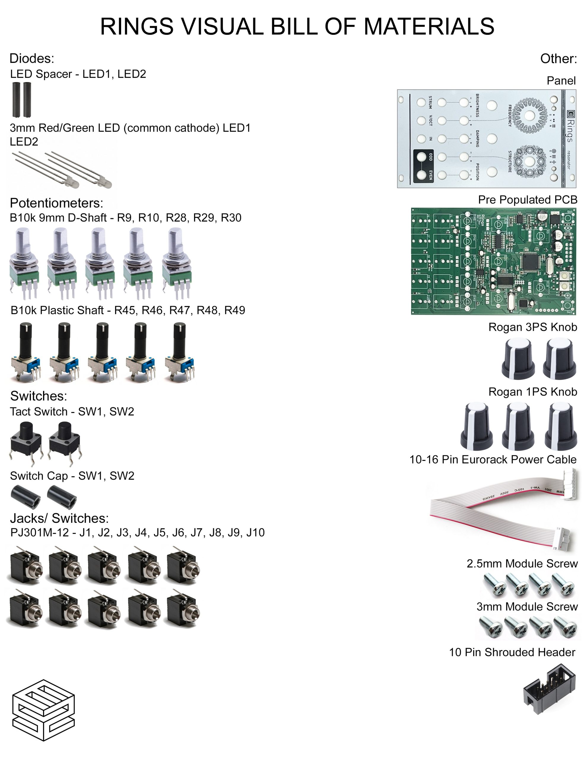
Click here for a bill of materials with Mouser part numbers.
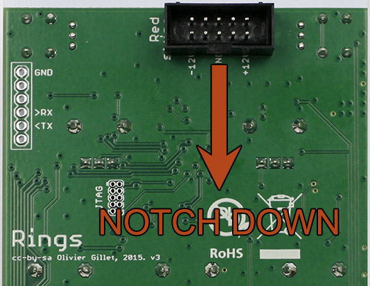
10 Pin Power Header
Our kit includes a keyed power header. Place the header on the rear of the board exactly as shown below, with the notch facing down. Carefully turn the project over to solder in place.
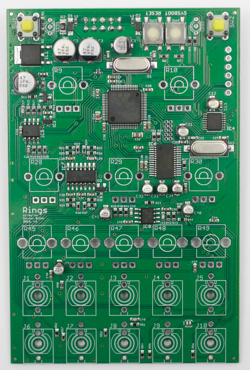
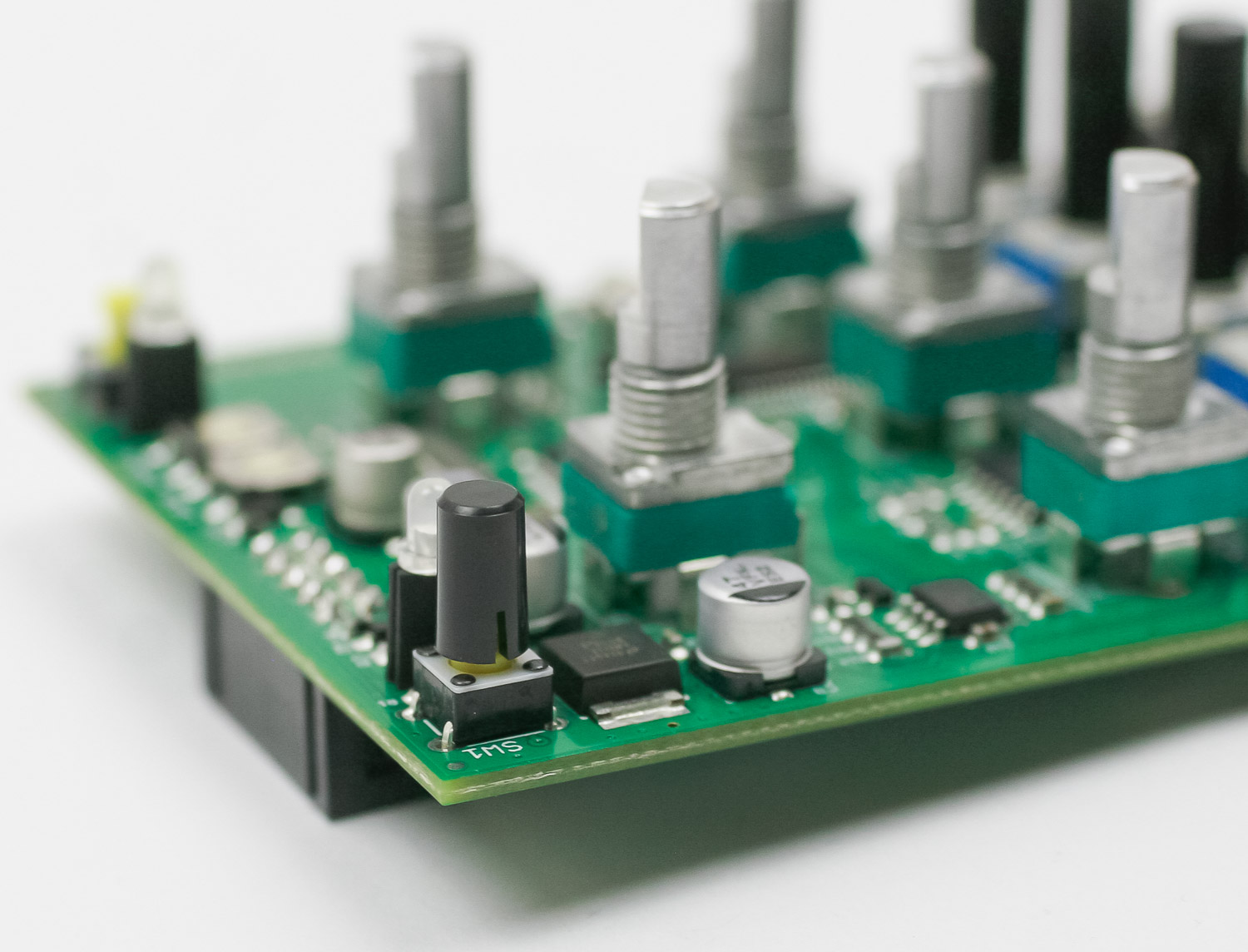
TACT SWITCHES
Place the two tact switches into the PCB as shown below, then carefully turn the project over to solder them in place.
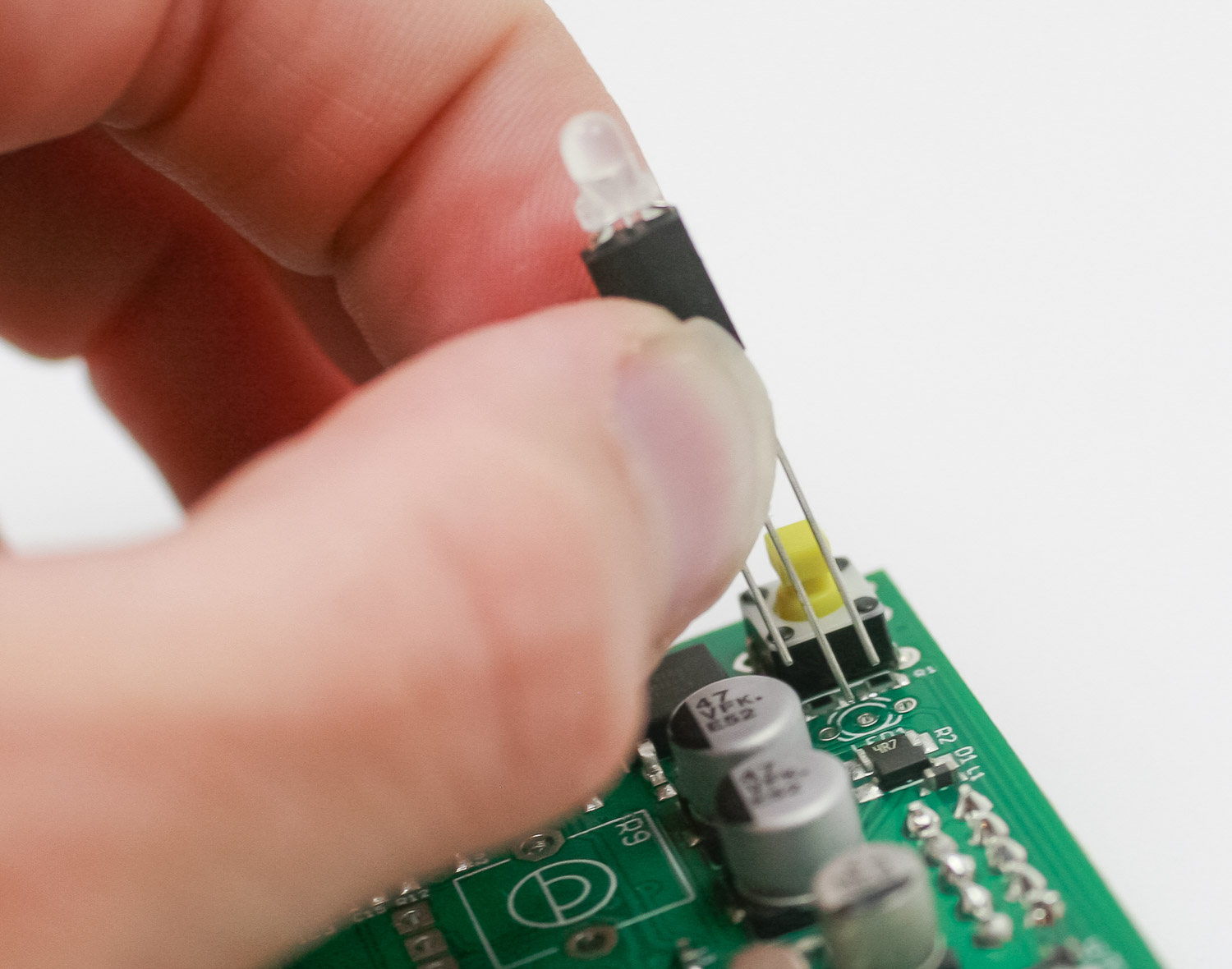
LEDs
First, slip the LED spacers on the LEDs.
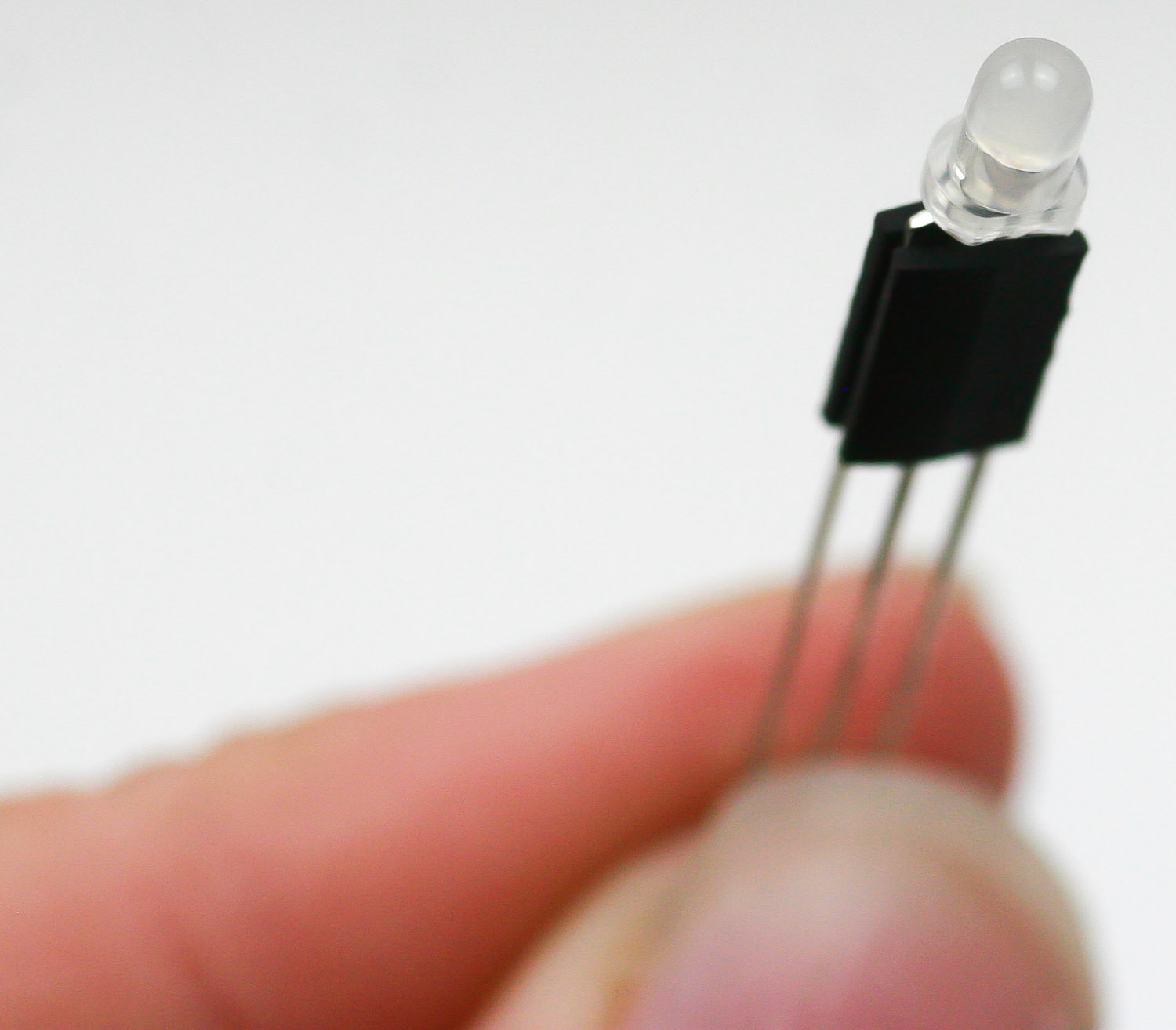
Now place the LEDs into the PCB by aligning the flat edge of the LED with the flat edge on the PCB silkscreen.
Do this for both sides
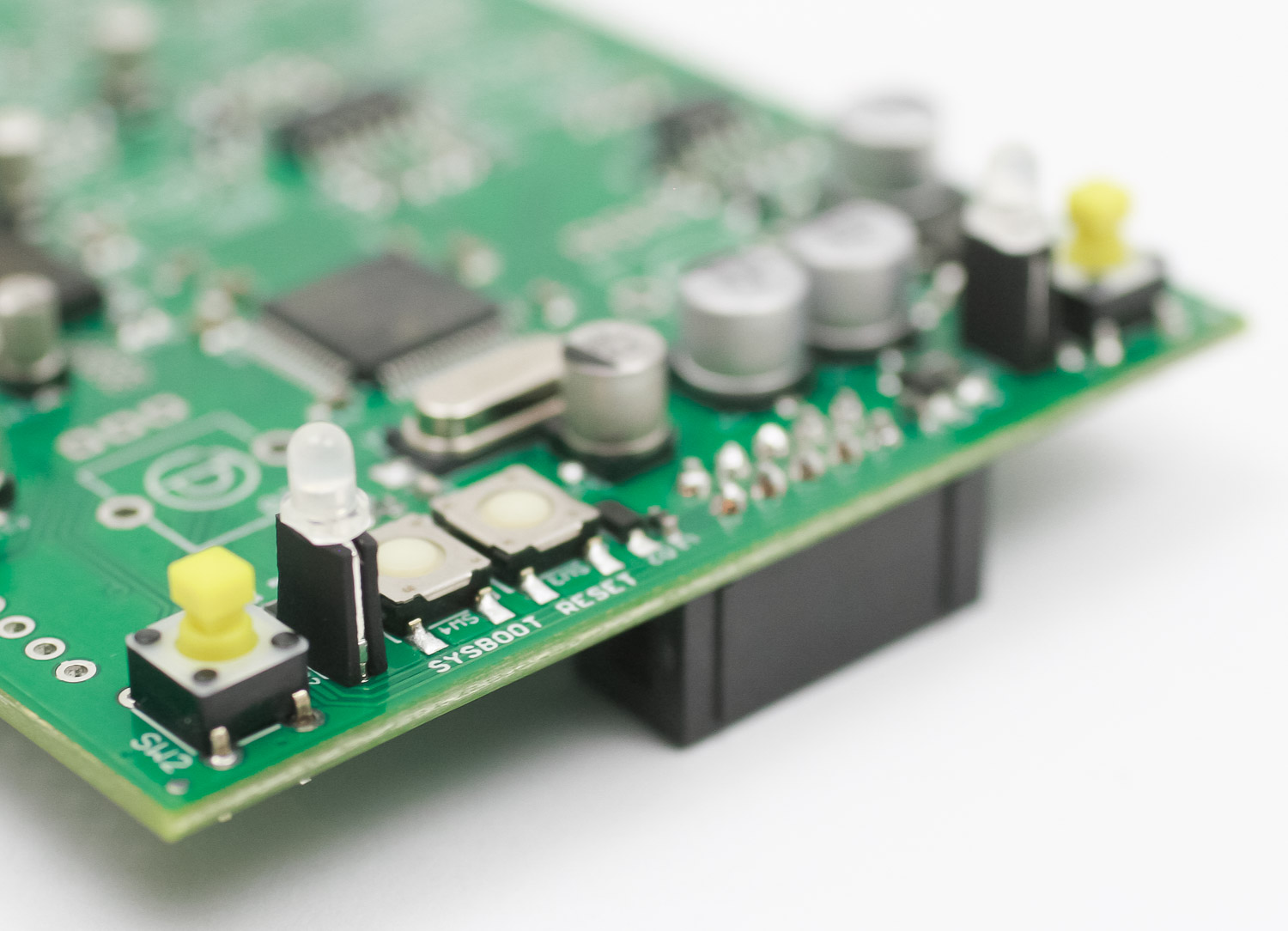
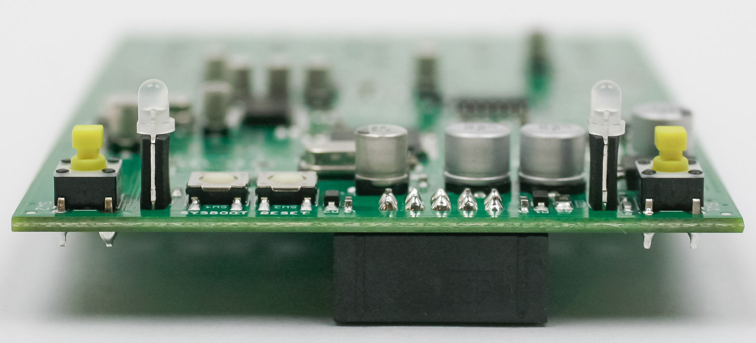
Carefully solder in place. Trim excess leads.
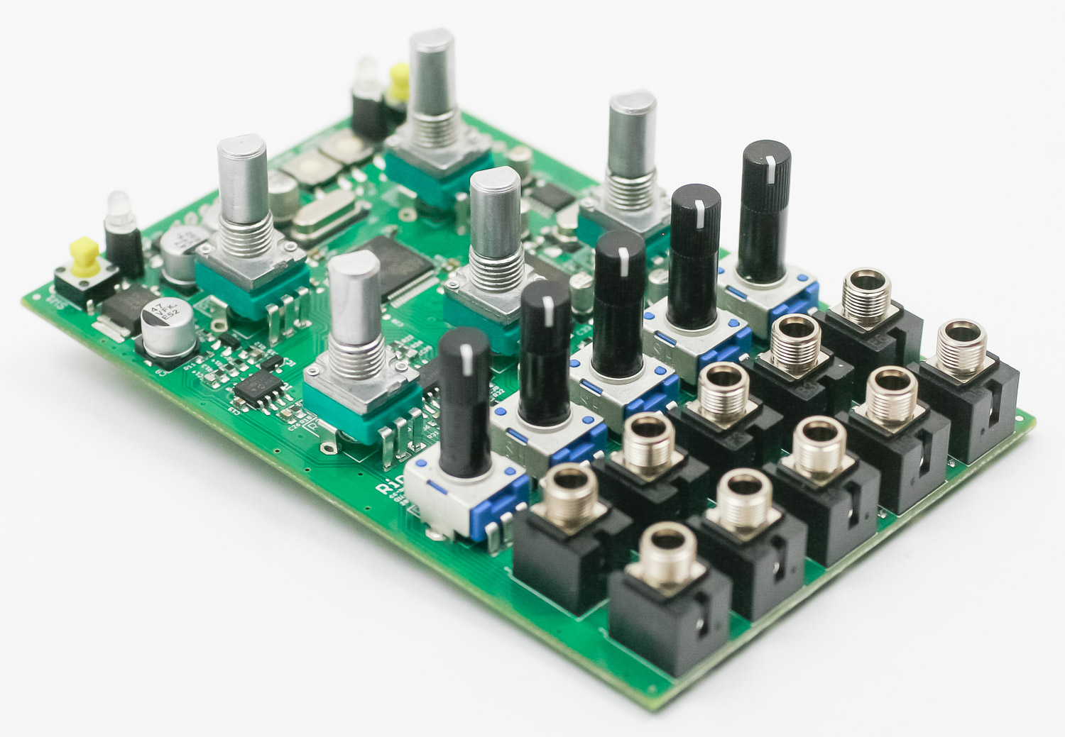
Jacks
Place the jacks into the PCB as shown below. Carefully turn the project over to solder in place. You can use the panel to make sure that the jacks all stay in place.

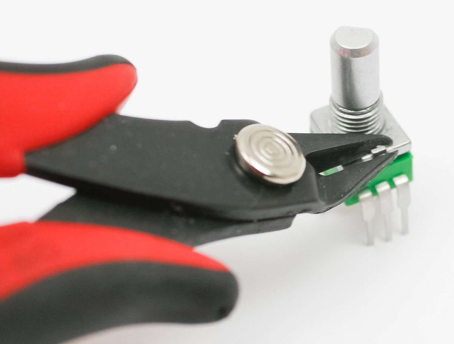
Potentiometers
If your pots have a tab (like the one below), make sure to trim them before assembly.
Place all of the pots into the PCB as shown below.

Carefully turn the project over to solder in place. Again, you can use the panel to make sure that the pots all stay in place.
Tact Switch Caps
Tightly press the tact switch caps on to the tact switches as shown below.

Panel
Carefully place the panel over your components as shown below. Take your time to make sure the LEDs don’t bend over.
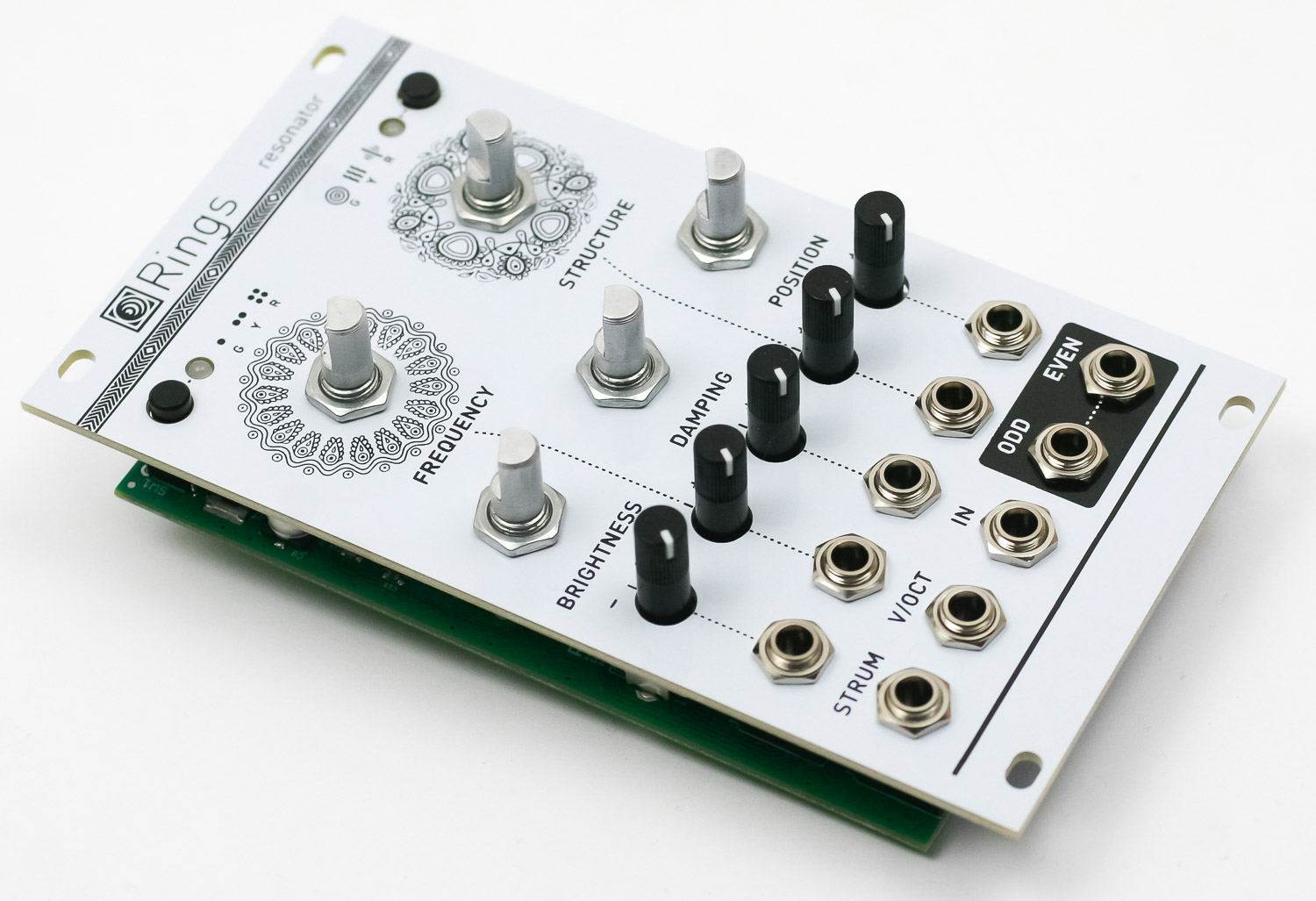
Now gently tighten the jack and pot nuts.
Knobs
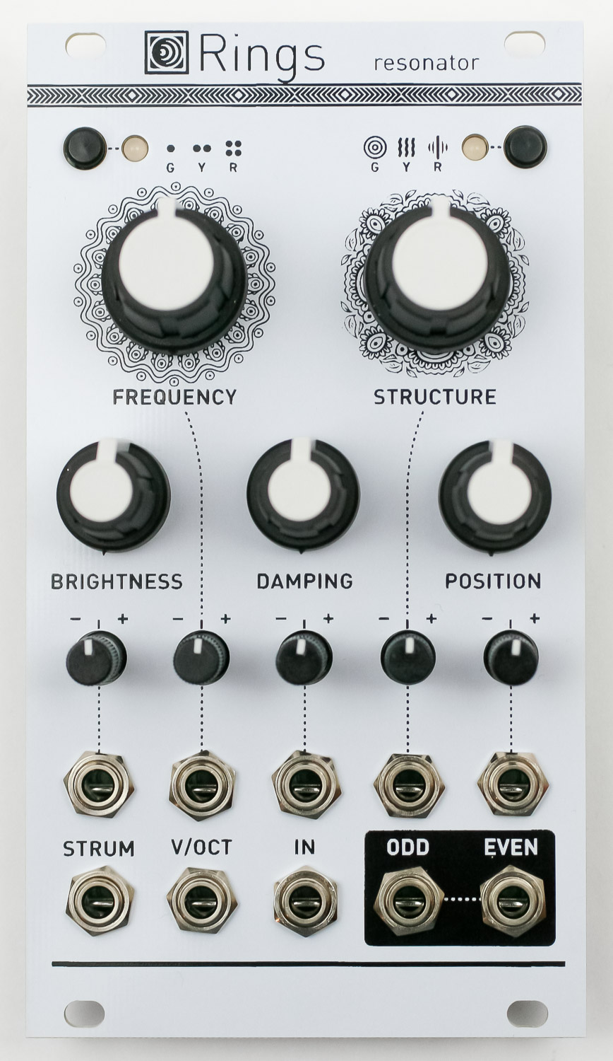
Place the knobs into the PCB as shown below and firmly press them in place. Notice that the two larger knobs are for “FREQUENCY” and “STRUCTURE.”
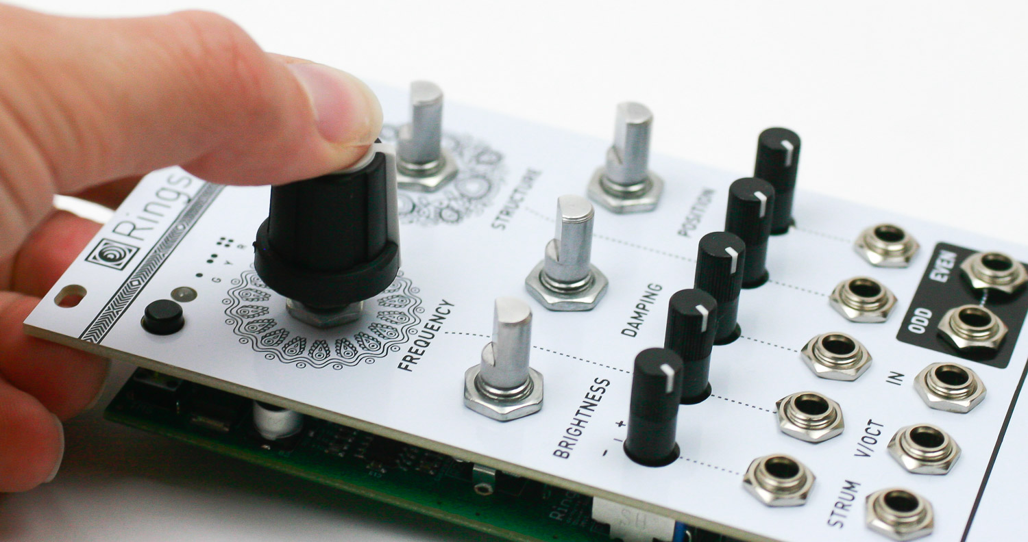
Repeat for the rest of the knobs.
Congrats! We’ve already programmed the firmware, so make sure the basic functions are working, and then move to the calibration below.
V/OCT Calibration procedure
- Disconnect all CV inputs.
- Connect the note CV output of a well-calibrated keyboard interface or MIDI-CV converter to the V/OCT input.
- Connect a patch cable to the FREQUENCY CV input. Leave the other end of the cable unplugged (this prevents the internal connection to +/- 1 semitone to be activated).
- Hold both buttons for two seconds. This is the “secret handshake” to enter the calibration procedure. The left LED blinks in orange.
- Play a C2 note, or send a 1V voltage from your CV source.
- Press the left button. The second LED blinks in orange.
- Play a C4 note, or send a 3V voltage from your CV source.
- Press the left button to complete the calibration. If the calibration is successful, the module returns to its normal state. Otherwise, the two LEDs will blink in RED for a couple of seconds.