Thank you for purchasing the Sound Study VID MIX!
ATTN: Please follow the BOM and these instructions. Don’t populate from the PCB silkscreen or these instruction pictures alone. Our components may look different from the pictures, so please look over your parts and check the codes first.
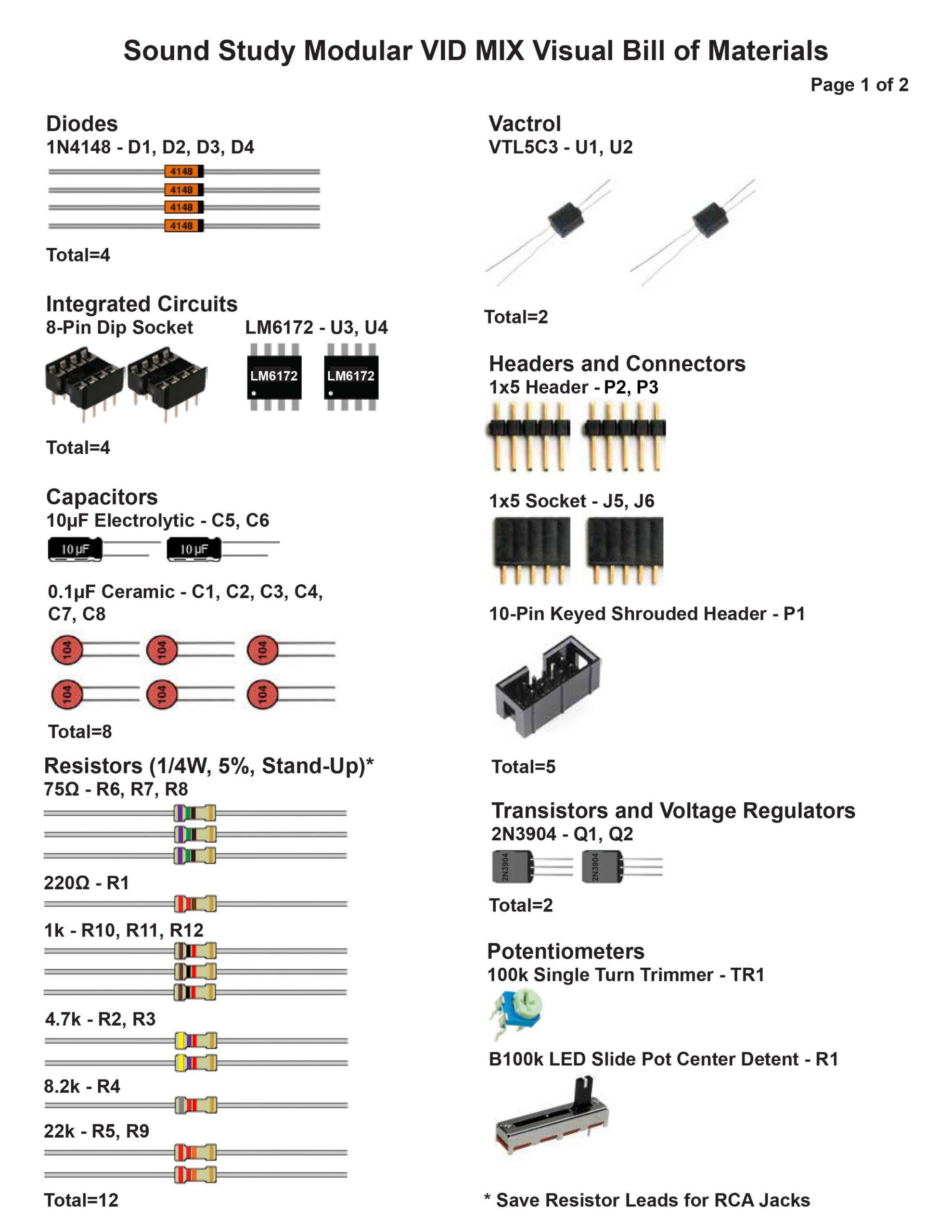
For a bill of materials with Mouser part numbers, click here.
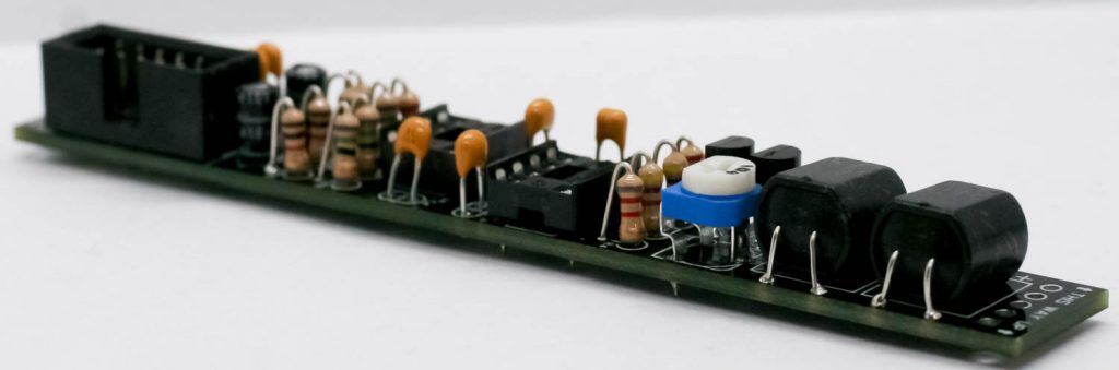
DIODES
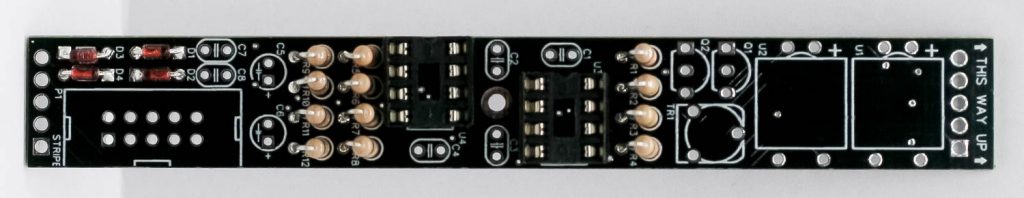
Take the four diodes and place them into the PCB as shown below. Diodes are polarized, so make sure you align the black stripe on the diode with the white stripe on the PCB. Carefully turn over and solder then trim lead excess.
IC SOCKETS
Place the IC sockets into the PCB by aligning the notch on the sockets with the sockets on the PCB silkscreen. Carefully turn over and solder in place.
RESISTORS
Next, place the resistors in the PCB in the “standup” configuration. Carefully turn over to solder in place.
ELECTROLYTIC CAPACITORS
Place the electrolytic capacitors into the PCB by placing the longer lead into the pad that has a “+” next to it. Turn over to solder and clip.
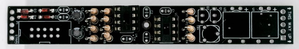
CERAMIC CAPCITORS
Place the ceramic caps into the PCB (they are not polarized), turn over to solder and clip.
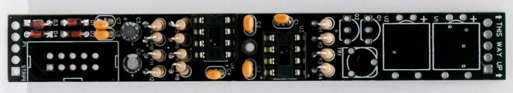
TRANSISTORS
Place the two transistors into the PCB by aligning the flat side with the flat side of the silk screen. Carefully turnover to solder and clip.
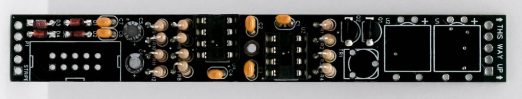
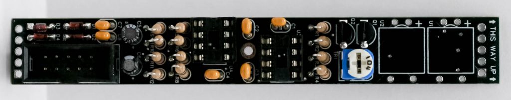
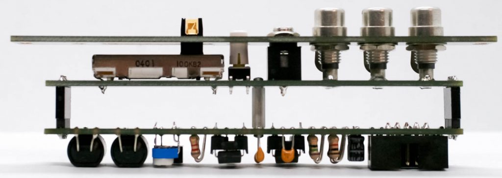
POWER SOCKET AND TRIM POT
Next, place the trimmer pot in and solder in place. Then place the 10 pin Eurorack power header in the PCB by aligning the notch in the socket with notch in the PCB silkscreen
VACTROLS
Place the Vactrols in to the PCB by aligning the the “+” marking on the Vactrol with the “+” marking on the PCB. Turn over to solder and clip.
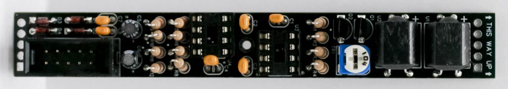
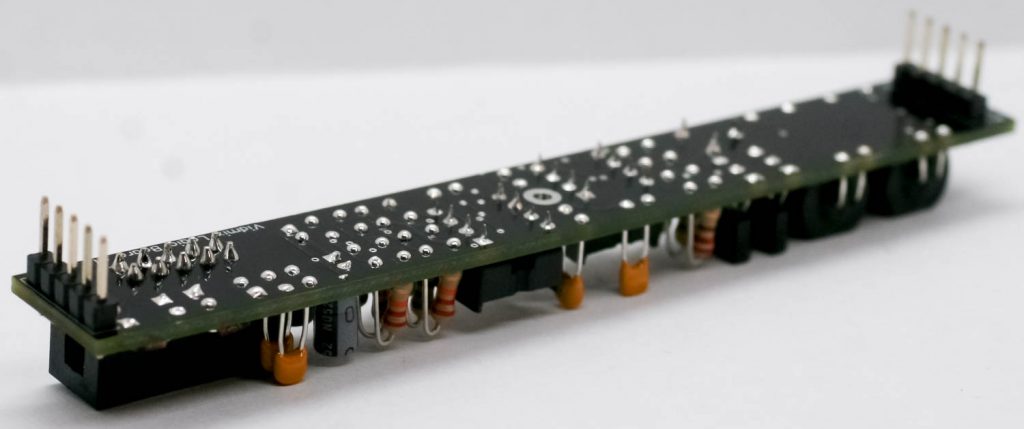
HEADER PINS & SOCKETS
Place the male header pins in the PCB as shown below. Carefully turn over to solder in place.
Do the same for the female header sockets on the control board. (Make sure you place these on the correct side!!!)
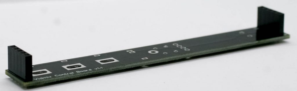
CONTROL BOARD SWITCH
Solder in the push button switch.
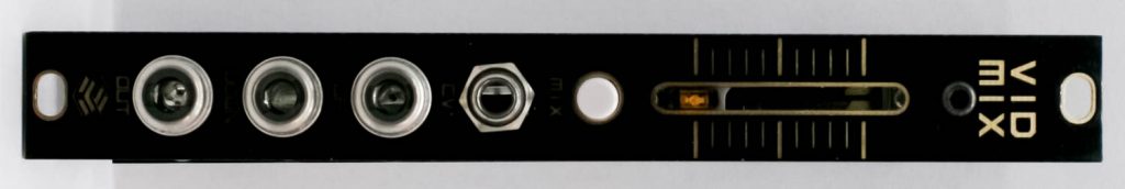
SLIDE POT & 3.5mm JACK
Solder in the slide pot and 3.5mm jack.
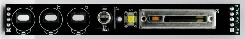
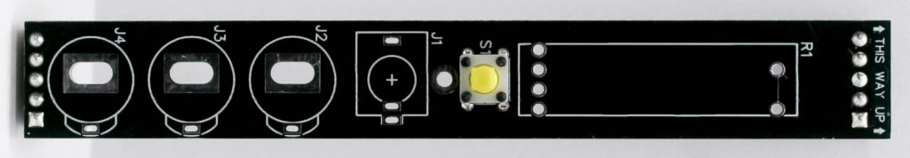
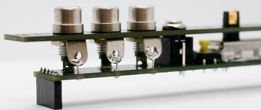
RCA JACKS
First secure the RCA jacks over the panel and bend over the ground tabs on the RCA jacks as shown below. You ocan then take the panel and put on the control board and tighten down the 3.5mm jack. You can then add the resistor clippings to the RCA jack tabs as shown below and solder them to the PCB. Clip excess leads.
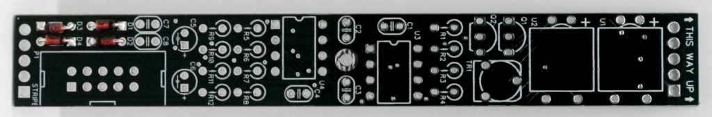
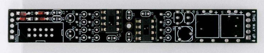
MAIN & CONTROL BOARD CONNECTION
Secure the two boards together using the standoff on the two provided screws as shown below.
You are now ready to mix some video!
CALIBRATION
Calibration is simple. Plug two video sources into the RCA inputs. Slide the pot all the way up, then turn the trimmer until you only see a clear image from one of your video inputs. Slide the pot all the way down, and you will have a clear image of the other video input. Lastly, set the slide pot at the center of its throw to blend the images; adjust the trimmer to taste.